
By Manudeepz | Arduino & DIY Electronics Projects
1. Introduction
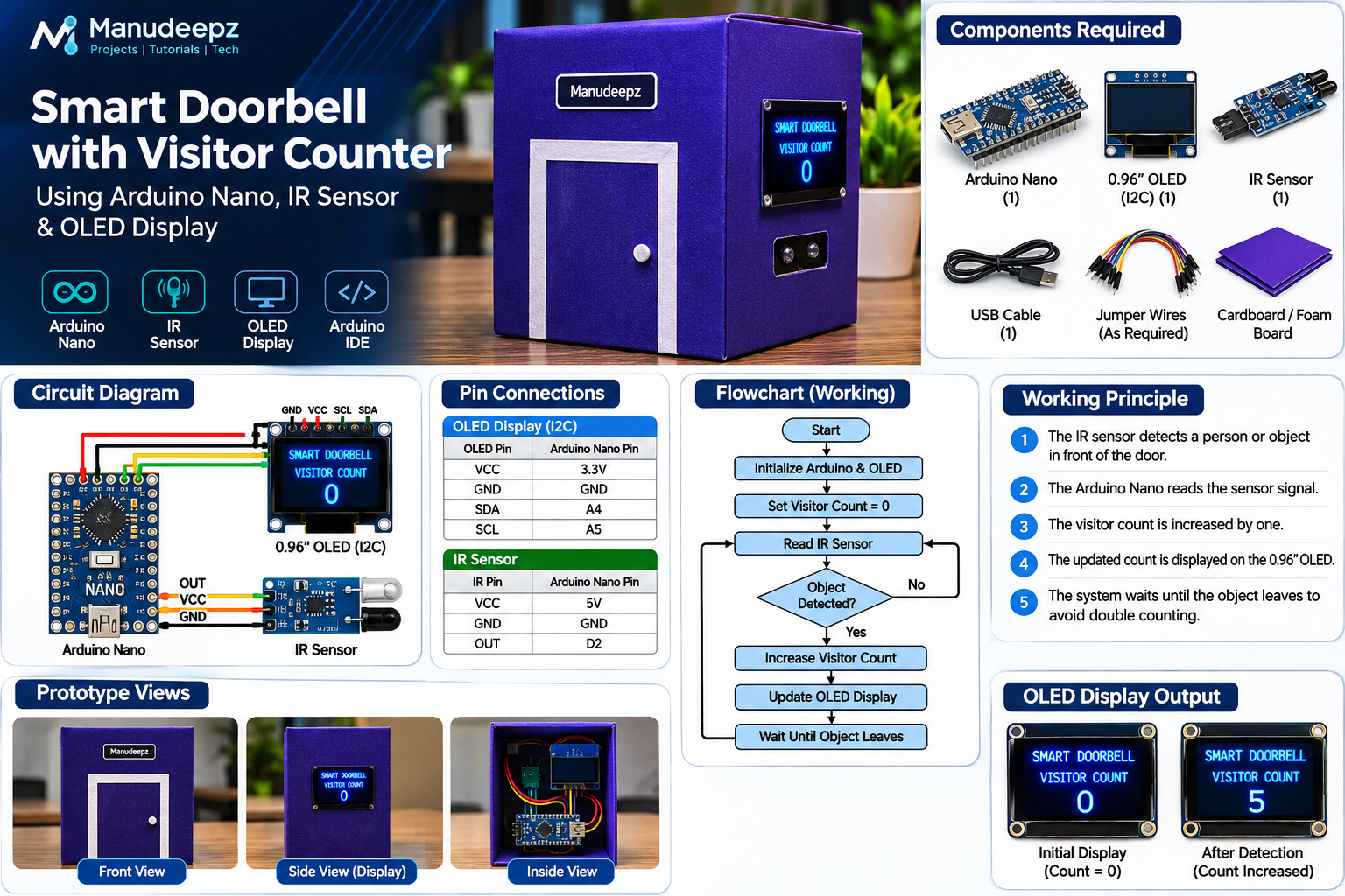
A Smart Doorbell with Visitor Counter is an Arduino-based electronics project designed to detect visitors and automatically count them.
The system uses an IR sensor to detect an object or person passing in front of it. An Arduino Nano processes the sensor signal and updates the visitor count on a 0.96-inch OLED display.
The prototype is built using a cardboard door model with an OLED display mounted on the right side of the enclosure.
This project is suitable for students, beginners, and electronics enthusiasts who want to learn Arduino programming, sensor interfacing, and OLED display integration.
2. Project Objectives
- Detect visitors using an IR sensor.
- Automatically increase the visitor count.
- Display the visitor count on an OLED screen.
- Prevent repeated counting while an object remains in front of the sensor.
- Build a low-cost physical smart doorbell prototype.
3. Components Required
| No. | Component | Quantity |
|---|---|---|
| 1 | Arduino Nano | 1 |
| 2 | 0.96-inch I2C OLED Display (128×64) | 1 |
| 3 | IR Obstacle Detection Sensor | 1 |
| 4 | Jumper Wires | As required |
| 5 | USB Cable | 1 |
| 6 | Cardboard Box / Foam Board | As required |
| 7 | Black or coloured chart paper | As required |
Note: This version does not include a buzzer. An audible doorbell can be added as a future enhancement.
4. Hardware Connections
OLED Display to Arduino Nano
| OLED Pin | Arduino Nano |
|---|---|
| VCC | 3.3V |
| GND | GND |
| SDA | A4 |
| SCL | A5 |
IR Sensor to Arduino Nano
| IR Sensor Pin | Arduino Nano |
|---|---|
| VCC | 5V |
| GND | GND |
| OUT | D2 |
Both modules share a common GND.
Important: The OLED used in this prototype works with a 3.3V supply. Check your particular OLED module’s voltage requirements before connecting it.
5. Software Requirements
The project is programmed using Arduino IDE.
Install these libraries from Arduino IDE → Library Manager:
- Adafruit GFX Library
- Adafruit SSD1306
The project uses the Wire library for I2C communication, which is included with the Arduino platform.
OLED I2C address: 0x3C
6. Complete Arduino Program (Without Buzzer)
The following code is used to detect visitors, count each detection once, and display the count on the OLED screen.
#include <Wire.h> #include <Adafruit_GFX.h> #include <Adafruit_SSD1306.h>#define SCREEN_WIDTH 128 #define SCREEN_HEIGHT 64 #define IR_PIN 2
Adafruit_SSD1306 display(128, 64, &Wire, -1);
int visitorCount = 0; int lastState = HIGH;
void setup() { pinMode(IR_PIN, INPUT);
Wire.begin();
if (!display.begin(SSD1306_SWITCHCAPVCC, 0x3C)) { while (true); }
display.clearDisplay(); display.setTextColor(SSD1306_WHITE);
showCount(); }
void loop() { int currentState = digitalRead(IR_PIN);
// Count once when the sensor detects an object if (currentState == LOW && lastState == HIGH) { visitorCount++; showCount();
// Wait until the object leaves the sensor while (digitalRead(IR_PIN) == LOW) { delay(20); }
delay(300); lastState = HIGH; } else { lastState = currentState; } }
void showCount() { display.clearDisplay();
display.setTextSize(1); display.setCursor(15, 5); display.println("SMART DOORBELL");
display.drawLine(0, 18, 127, 18, SSD1306_WHITE);
display.setTextSize(1); display.setCursor(25, 25); display.println("VISITOR COUNT");
display.setTextSize(3); display.setCursor(48, 40); display.print(visitorCount);
display.display(); }
Important: This code assumes that the IR sensor output becomes LOW when an object is detected. If your sensor uses the opposite output logic, the detection condition must be changed.
7. How Does the Program Work?
Step 1: Library Initialization
The program includes the Wire, Adafruit GFX, and Adafruit SSD1306 libraries. These libraries enable I2C communication and OLED display control.
Step 2: Pin Configuration
The IR sensor output is connected to digital pin D2. The Arduino reads the sensor state using digitalRead().
Step 3: OLED Initialization
The OLED display is initialized using I2C address 0x3C.
The initial screen displays:
- SMART DOORBELL
- VISITOR COUNT
- 0
Step 4: Object Detection
The IR sensor detects an object passing in front of it and sends a LOW signal to the Arduino.
Step 5: Visitor Counting
When the sensor changes from HIGH to LOW, the visitor count increases by one.
Step 6: Preventing Double Counting
The program waits until the object leaves the sensor detection area. This prevents repeated counting while the object remains in front of the sensor.
Step 7: OLED Update
The showCount() function refreshes the OLED display with the latest visitor count.
8. Program Flowchart
START


          v
  Initialize Arduino
  Initialize OLED


          v
  Display Visitor Count


          v
  Read IR Sensor


          v
  Object Detected?
        /
      NO       YES


     +---------+


          v
       Repeat Loop
9. Physical Prototype Construction
A miniature door model is created using a cardboard box.
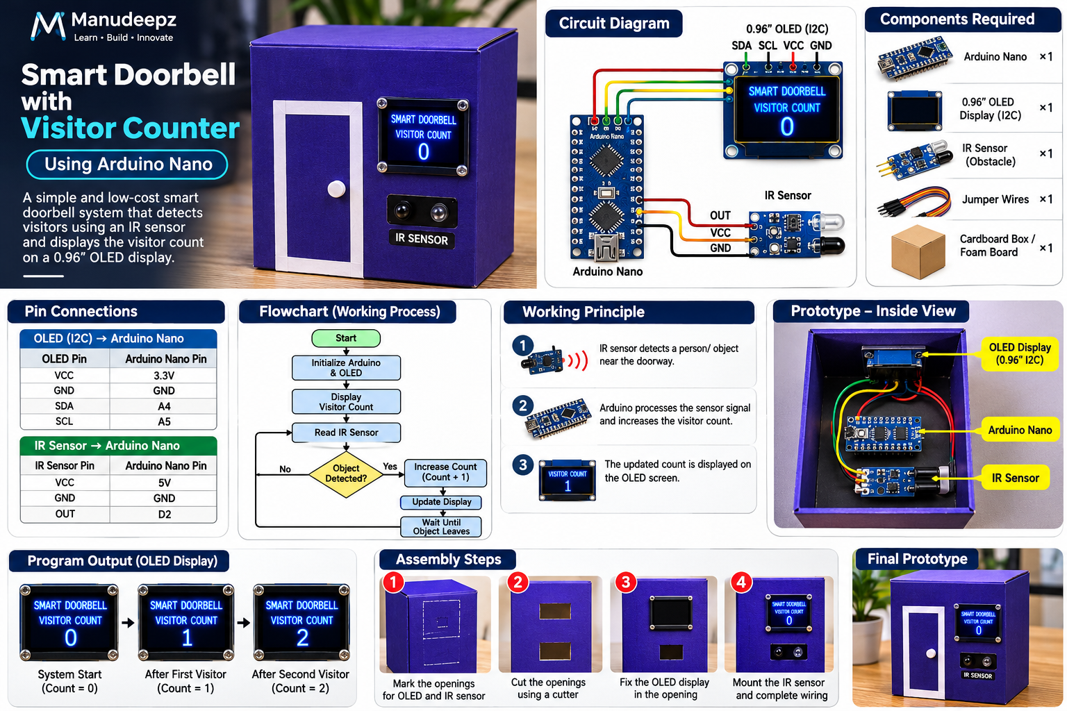
The OLED display is mounted on the right side of the box, while the IR sensor is positioned so that it can detect objects passing through the sensing area.
The Arduino Nano and connecting wires are placed inside the enclosure.
Assembly Procedure
- Prepare a cardboard box for the prototype.
- Mark a rectangular opening on the right side for the OLED display.
- Cut the opening carefully according to the OLED dimensions.
- Fix the OLED display behind the opening.
- Create an opening for the IR sensor and position it facing the detection area.
- Place the Arduino Nano securely inside the box.
- Connect the OLED and IR sensor according to the circuit connections.
- Connect the USB cable to power the Arduino Nano.
- Upload the program and test the complete system.
10. Testing Procedure
| Test | Action | Expected Result |
|---|---|---|
| Power Test | Switch on the Arduino | OLED starts and displays count 0 |
| Detection Test | Place a hand in front of IR sensor | Count increases by 1 |
| Hold Test | Keep the hand in front of sensor | Count should not increase repeatedly |
| Reset Detection | Remove the hand | Sensor becomes ready for the next detection |
| Repeat Test | Place the hand again | Count increases by 1 again |
The visitor count is stored in the Arduino’s RAM in this version. It returns to zero when the Arduino restarts or loses power.
11. Applications
- Smart home entrance demonstrations
- Visitor counting systems
- Educational electronics projects
- Arduino and sensor interfacing experiments
- Basic entrance monitoring prototypes
12. Future Enhancements
The project can be improved by adding:
- Active buzzer for an audible doorbell alert.
- Reset button to clear the visitor count.
- EEPROM storage to retain the count after power loss.
- Wi-Fi notifications using an ESP32 or suitable Wi-Fi module.
- A more durable enclosure using a 3D-printed case.
13. Conclusion
The Smart Doorbell with Visitor Counter demonstrates how an Arduino Nano, IR sensor, and OLED display can be integrated to build a simple visitor-counting system.
The prototype successfully demonstrates object detection, visitor counting, and real-time OLED display updates.
It is a low-cost and beginner-friendly project that introduces important concepts in embedded systems and electronics.
Project Developed by Manudeepz
Learn • Build • Innovate
